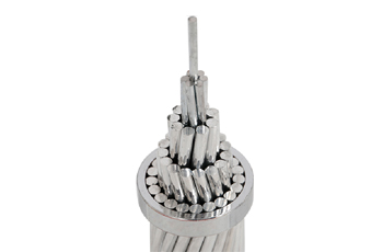


Table 1 BS Standard
| Nominal area of cross-section of stranded conductor mm2 |
Construction (stranding and wire diameter) number/mm |
Overall diameter of conductor (approx.) mm |
Nominal mass per unit length kg/km |
Resistance at 20℃ | Minimum breaking load N |
|
| Nominal /km |
Max. /km |
|||||
| 10 | 7/1.35 | 4.05 | 89.82 | 1.788 | 1.829 | 3752 |
| 14 | 7/1.60 | 4.8 | 126.2 | 1.273 | 1.303 | 5267 |
| 16 | 3/2.65 | 5.7 | 148.3 | 1.082 | 1.106 | 6194 |
| 16 | 7/1.70 | 5.1 | 142.4 | 1.128 | 1.154 | 5946 |
| 25 | 7/2.10 | 6.3 | 217.3 | 0.7391 | 0.7563 | 9073 |
| 32 | 3/3.75 | 8.06 | 296.9 | 0.5405 | 0.552 | 12400 |
| 32 | 7/2.46 | 7.38 | 298.2 | 0.5386 | 0.5497 | 12442 |
| 35 | 7/2.50 | 7.5 | 308 | 0.5215 | 0.5337 | 12860 |
| 50 | 7/3.00 | 9 | 443.5 | 0.3622 | 0.3706 | 18520 |
| 50 | 19/1.80 | 9 | 435.8 | 0.3727 | 0.3819 | 17700 |
| 70 | 7/3.55 | 10.65 | 621.1 | 0.2586 | 0.2646 | 25930 |
| 70 | 19/2.10 | 10.5 | 593.2 | 0.2738 | 0.2806 | 24090 |
| 95 | 19/2.50 | 12.5 | 840.7 | 0.1932 | 0.198 | 34140 |
| 100 | 7/4.30 | 12.9 | 911.2 | 0.1763 | 0.181 | 36540 |
| 120 | 19/2.80 | 14 | 1055 | 0.154 | 0.1578 | 42830 |
| 125 | 19/2.90 | 14.5 | 1131 | 0.1436 | 0.1471 | 45940 |
| 150 | 19/3.20 | 16 | 1377 | 0.118 | 0.1208 | 55940 |
| 150 | 37/2.25 | 15.75 | 1334 | 0.1233 | 0.1264 | 53880 |
| 185 | 19/3.55 | 17.75 | 1695 | 0.09582 | 0.09815 | 68860 |
| 185 | 37/2.50 | 17.5 | 1647 | 0.09981 | 0.1024 | 66490 |
Table 2 AS/NZS Standard
| Number of stranding | Wire diameter mm | Approx. overall diameter mm | Cross-sectional area mm2 | Mass per km
kg |
Calculated breaking load kN | Equivalent aluminium area mm2 | DC resistance km at 20℃ |
| 7 | 1.00 | 3.00 | 5.498 | 49.3 | 2.32 | 8.68 | 3.25 |
| 7 | 1.25 | 3.75 | 8.589 | 76.9 | 3.59 | 13.6 | 2.09 |
| 7 | 1.75 | 5.25 | 16.84 | 151 | 6.89 | 26.6 | 1.06 |
| 7 | 2.00 | 6.00 | 21.99 | 197 | 8.89 | 34.7 | 0.815 |
| 7 | 2.75 | 8.25 | 41.58 | 375 | 16.2 | 65.3 | 0.433 |
| 19 | 1.75 | 8.75 | 45.7 | 413 | 18.3 | 71.7 | 0.395 |
| 19 | 2.00 | 10.00 | 59.7 | 538 | 23.6 | 93.6 | 0.303 |
| 7 | 3.50 | 10.50 | 67.35 | 607 | 25.4 | 106 | 0.268 |
| 7 | 3.75 | 11.30 | 77.28 | 696 | 28.8 | 121 | 0.233 |
| 37 | 1.75 | 12.30 | 88.99 | 806 | 35.6 | 139 | 0.203 |
| 19 | 2.75 | 13.80 | 112.9 | 1020 | 43.1 | 177 | 0.160 |
| 19 | 3.00 | 15.00 | 134.3 | 1210 | 50.8 | 211 | 0.134 |
| 37 | 2.50 | 17.50 | 181.6 | 1640 | 70.3 | 284 | 0.0996 |
| 37 | 2.75 | 19.30 | 219.8 | 1990 | 83.9 | 344 | 0.0826 |
| 37 | 3.00 | 21.00 | 261.6 | 2370 | 98.9 | 409 | 0.0691 |
| 61 | 2.75 | 24.80 | 362.3 | 3290 | 138 | 566 | 0.5000 |