


Table 1 H1Z2Z2-K
| Size
mm2 |
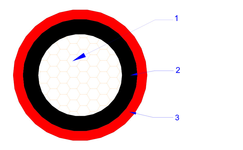
Conductor Dia. mm | Nominal insulation thickness mm | Nominal Jacket thickness mm | Approx. Cable Dia. mm | Approx. Cable Weight kg/km | 20℃ Max. DC resistance Ω/km |
| 1×1.5 | 1.58 | 0.7 | 0.8 | 4.6 | 35 | 13.7 |
| 1×2.5 | 2.02 | 0.7 | 0.8 | 5.0 | 47 | 8.21 |
| 1×4 | 2.58 | 0.7 | 0.8 | 5.6 | 65 | 5.09 |
| 1×6 | 3.17 | 0.7 | 0.8 | 6.2 | 87 | 3.39 |
| 1×10 | 4.1 | 0.7 | 0.8 | 7.6 | 132 | 1.95 |
| 1×16 | 5.6 | 0.7 | 0.9 | 8.8 | 197 | 1.24 |
| 1×25 | 7.1 | 0.9 | 1.0 | 10.9 | 303 | 0.795 |
| 1×35 | 8.5 | 0.9 | 1.1 | 12.5 | 410 | 0.565 |
| 1×50 | 10.2 | 1.0 | 1.2 | 14.6 | 573 | 0.393 |
| 1×70 | 12.0 | 1.1 | 1.2 | 16.6 | 777 | 0.277 |
| 1×95 | 14.0 | 1.1 | 1.3 | 18.8 | 1030 | 0.210 |
| 1×120 | 16.0 | 1.2 | 1.3 | 21.0 | 1284 | 0.164 |
| 1×150 | 17.0 | 1.4 | 1.4 | 22.6 | 1594 | 0.132 |
| 1×185 | 19.0 | 1.6 | 1.6 | 25.4 | 1979 | 0.108 |
| 1×240 | 22.0 | 1.7 | 1.7 | 28.8 | 2540 | 0.0817 |